Connecting workflow elements
Figure 9.7 explains the different parts of a workflow element.
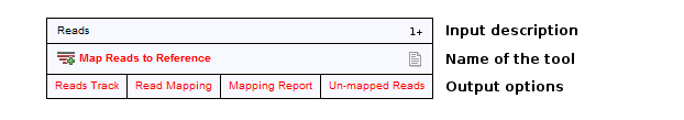
Figure 9.7: A workflow element consists of three parts: input, name of the tool, and output.
At the top of each element a description of the required type of input is found. In the right-hand side, a symbol specifies whether the element accepts multiple incoming connections, e.g. +1 means that more than one output can be connected, and no symbol means that only one can be connected. At the bottom of each element there are a number of small boxes that represent the different kinds of output that is produced. In the example with the read mapper shown in figure 9.2, the read mapper is able to produce a reads track, a report etc.
Each of the output boxes can be connected to further analysis in three ways:
- By dragging with the mouse from the output into the input box of the next element. This is shown in figure 9.8. A green border around the box will tell you when the mouse button can be released, and an arrow will connect the two elements (see figure 9.9).
- Right-clicking the output box will display a list of the possible elements that this output could be connected to. You can also right-click the input box of an element and connect this to a matching output of another element.
- Alternatively, if the element to connect to is not already added, you can right-click the output and choose Add Element to be Connected. This will bring up the dialog from figure 9.1, but only showing the tools that accepts this particular output. Selecting a tool will both add it to the workflow and connect with the output you selected. You can also add an upstream element of workflow in the same way by right-clicking the input box.
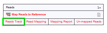
Figure 9.8: Dragging the reads track output with the mouse.
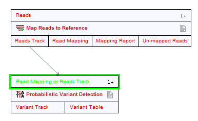
Figure 9.9: The reads track is now used for variant calling.
All the logic of combining output and input is based on matching the type of input. So the read mapper creates a reads track and a report as output. The variant caller accepts reads tracks as input but not mapping reports. This means that you will not be able to connect the mapping report to the variant caller.