Configuring workflow elements
Each of the tools can be configured by right-clicking the name of the tool as shown in figure 9.3.
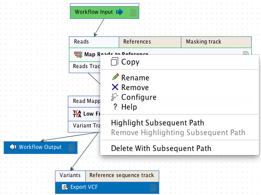
Figure 9.3: Configuring a tool.
The first option you are presented with is the option to Rename the element. This can be useful when you wish to discriminate between several copies of the same tool in a workflow. The name of the element is also visible as part of the process description when the workflow is run. To rename the element, right click on the tool in the workflow and select the "Rename" option, or click on the tool in the workflow and then press the F2 key.
The Remove option is used to remove elements from the workflow. The shortcut Alt + Shift + R removes all elements from the workflow.
You can also configure a given element using the Configure option from the right click menu or by double-clicking on the element. This opens a dialog with options for setting parameters, selecting reference data, selecting the export destination of specified columns, etc. An example is shown in figure 9.4.
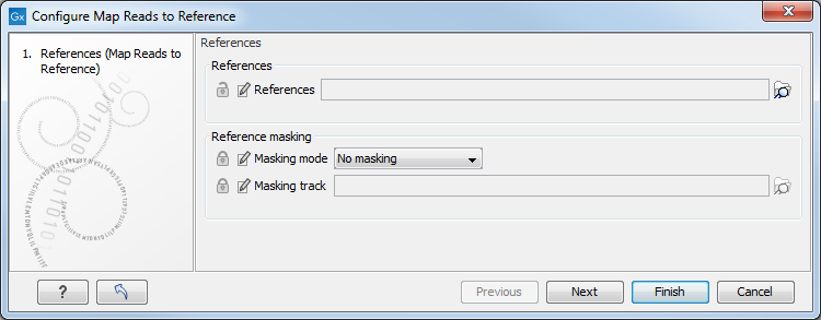
Figure 9.4: Configuring read mapper parameters.
Click through the dialogs using Next and press Finish when you are done. This saves the parameter settings for that tool. These are then applied when the workflow is executed.
You can also change the name of a parameter if you so wish, for example, to help with usability for the intended users of a workflow. To do this, click on the edit icon (![]() ) and enter a new name.
) and enter a new name.
Special consideration should be given when configuring reference data in a workflow. For example, when configuring a read mapping tool, such as shown in figure 9.3, you have to define a reference genome that sequences will be mapped to. You configure this by selecting data in the Navigation Area. If you distribute the workflow and it is installed on a different system, where that data is not accessible in same relative location, the workflow installation procedure will involve defining new reference data to use. This is explained in more detail in Installing a workflow in the Workbench.
The lock icons in the dialog are used for specifying whether the parameter should be locked and unlocked as described in Locking and unlocking parameters. Locking parameters means that the workflow will be run with the same parameters every time; the user will not be prompted to supply values for locked parameters when they launch the workflow.
Once an element has been configured, the workflow element will be shaded with a darker color to help in distinguishing which elements have been configured.
The Highlight Subsequent Path option causes the element that was clicked on, and all the elements downstream of that one, to be highlighted. Other elements will be grayed out (figure 9.5). The Remove Highlighting Subsequent Path option reverts the highlighting, returning to the normal workflow layout.
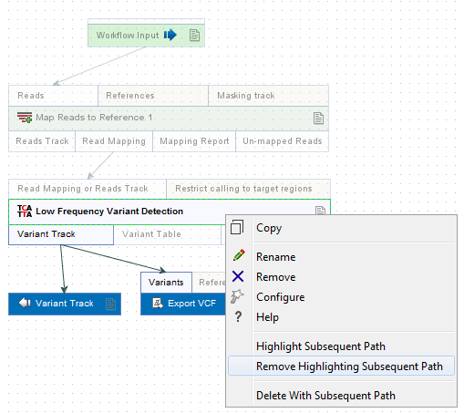
Figure 9.5: Highlight path from the selected tool and downstream.
In some workflows, many elements use the same reference data. There is a quick way of configuring these: right-click on the empty space and choose Configure All References. A dialog then appears listing all the reference data needed by the workflow. When you click on the button labeled Finish, only the elements where the 'active' column is checked will be configured.
Similarly, instead of configuring the various tools individually, the Configuration Editor enables the specification of all settings, references, masking parameters etc. through a single wizard window (figure 9.6). This editor is accessed through the (![]() ) icon located in the lower left corner.
) icon located in the lower left corner.
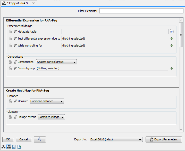
Figure 9.6: The Configuration Editor can be used configure all the tools that can be configured in a given Workflow.